Finished up a little project last week that had some interesting facets, so i thought the members here might like to have a look.
I am doing a bit of work on the power train of a 1914 Mercer....Lots to do here, gearbox, axles, differential, all in need of work.
First part of the project was to fit new ring and pinion to the final drive. Before that can be assembled (not my part of the task) the carrier for the
differential (spider and bevel gears) and ring gear have to be in good shape.
Original carrier had been worked on by another shop, and someone had constructed a new right half for the carrier. Not a bad job, but there were some problems needing
attention. Further the "cross" that carries the spider gears had failed. A new cross was made with larger location diameters , so the carrier needed to be modified to suit.
Unfortunately the original and mating half of the carrier (the left side) was not good...It was worn and did not register to the re-made right half.....Decision was made to replace
with a new part to get everything to run straight and round, while holding the new larger spider gear cross....
Basic part was roughed out both inside and out on the Romi....Some tricky parts of this work getting the inside profile with undercut top be shaped to match the outside...required 3
different tool setups owing to the undercut and the island in the middle.(tool relief and clearance issues) Won't bore everyone here about doing the lathe work as this was pretty
straight forward sans the inside profile.....
Anyhow after getting the shape done i needed to cut in "windows" for gear clearance and oil flow......
![]()
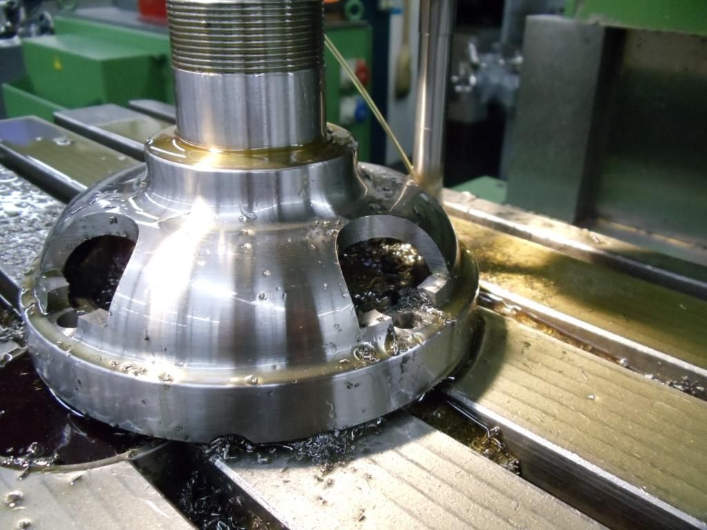
Here i am roughing out the windows. Of note is the length of the end mill...1/2' cutter necked down with 1/2" length of cut...needed long tool to be able to reach past the bearing mount and thread.
Note the stair step in the rough cut...this will be trimmed later to give a blend radius...
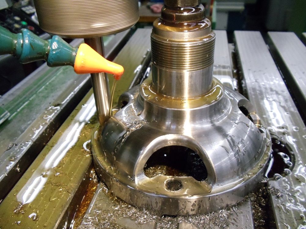
Once the window was roughed out, i profiled the edge to blend from the cutout to the outside surface and generate the fillet that connects the floor....
Programming done here via SurfCam form a Solid works model.....Cutter is solid carbide 1/2" ball endmill. Having just gotten my DNC back online ,this was the first real running test for a long
program...Think this took something like 20K lines of code to run....Too much for a standard Dialog 4 without the DNC option.
![]()
![]()
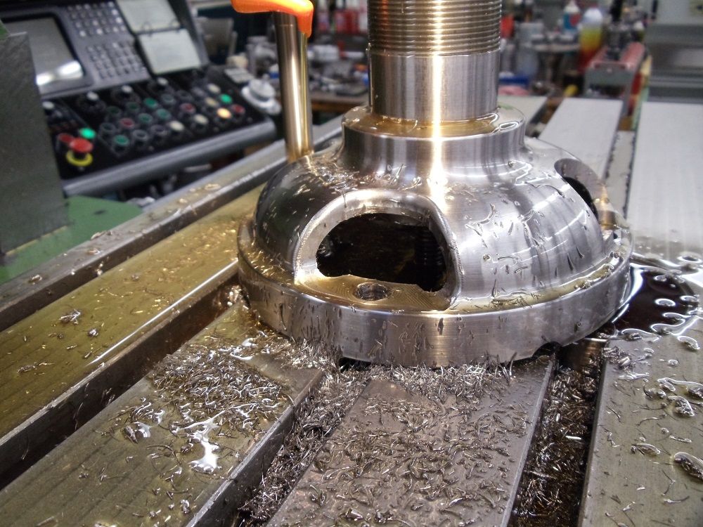
Used a fairly coarse surface roughness as i wanted to keep the machine time down.....
![]()
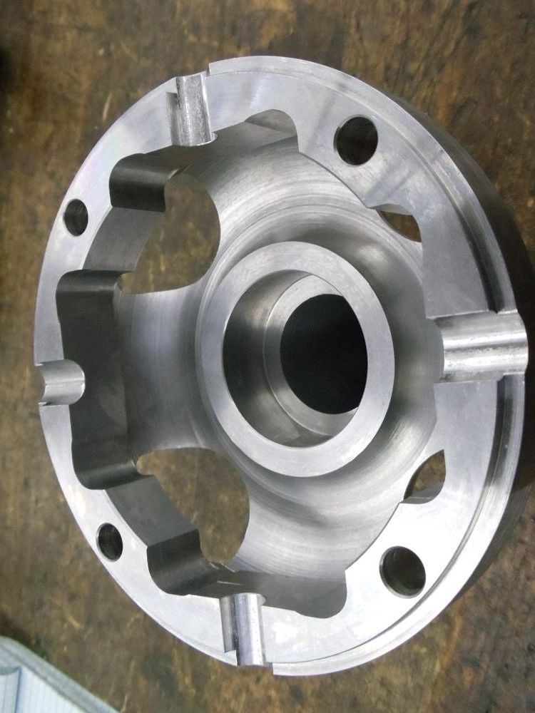
Shot of the simi-finished inside of the housing....Windows are finished, bolt holes finished. The center bore will mount a bushing to support the bevel gear at the end of the axles.
4 notches have been roughed with a ball end mill into the parting face to start the seats for the center cross.....The inside contour with under cut can be seen. Also note the 4 flats at the
inside face of the cross notches...These flat faces will be later surfaced to form the thrust face for the spider gears....
More to follow......................
Cheers Ross
I am doing a bit of work on the power train of a 1914 Mercer....Lots to do here, gearbox, axles, differential, all in need of work.
First part of the project was to fit new ring and pinion to the final drive. Before that can be assembled (not my part of the task) the carrier for the
differential (spider and bevel gears) and ring gear have to be in good shape.
Original carrier had been worked on by another shop, and someone had constructed a new right half for the carrier. Not a bad job, but there were some problems needing
attention. Further the "cross" that carries the spider gears had failed. A new cross was made with larger location diameters , so the carrier needed to be modified to suit.
Unfortunately the original and mating half of the carrier (the left side) was not good...It was worn and did not register to the re-made right half.....Decision was made to replace
with a new part to get everything to run straight and round, while holding the new larger spider gear cross....
Basic part was roughed out both inside and out on the Romi....Some tricky parts of this work getting the inside profile with undercut top be shaped to match the outside...required 3
different tool setups owing to the undercut and the island in the middle.(tool relief and clearance issues) Won't bore everyone here about doing the lathe work as this was pretty
straight forward sans the inside profile.....
Anyhow after getting the shape done i needed to cut in "windows" for gear clearance and oil flow......
Here i am roughing out the windows. Of note is the length of the end mill...1/2' cutter necked down with 1/2" length of cut...needed long tool to be able to reach past the bearing mount and thread.
Note the stair step in the rough cut...this will be trimmed later to give a blend radius...
Once the window was roughed out, i profiled the edge to blend from the cutout to the outside surface and generate the fillet that connects the floor....
Programming done here via SurfCam form a Solid works model.....Cutter is solid carbide 1/2" ball endmill. Having just gotten my DNC back online ,this was the first real running test for a long
program...Think this took something like 20K lines of code to run....Too much for a standard Dialog 4 without the DNC option.
Used a fairly coarse surface roughness as i wanted to keep the machine time down.....
Shot of the simi-finished inside of the housing....Windows are finished, bolt holes finished. The center bore will mount a bushing to support the bevel gear at the end of the axles.
4 notches have been roughed with a ball end mill into the parting face to start the seats for the center cross.....The inside contour with under cut can be seen. Also note the 4 flats at the
inside face of the cross notches...These flat faces will be later surfaced to form the thrust face for the spider gears....
More to follow......................
Cheers Ross