Shop is quite busy these days. Weather turning nice (80*f today) and with that our customers start ramping up for another Vintage Racing season.....
Have a very good customer who has been running a Typo 61 (Maserati Birdcage) for the last few seasons....Gives the car a good workout and this year he is changing out
the engine block, for a new (reproduction) unit. Engine cases have a lifespan. This is a 4 cylinder block with wet liners (CI) originally built as a 1600CC design...and expanded over
the years by the factory to its final 2.9 L displacement. Expanding the bore has the down side of reducing the internal thickness of the some of the block structural members, and hence the reduced life..
Replacement blocs come from Brian Heart in the UK.......So much for the short history.
as with things made on a "Short or limited Run" basis often differences exist between "similar" parts.....no exception in the case of this block!
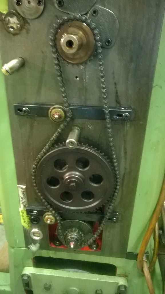
First step in making a block swap is to measure everything, and do a test assembly.This includes laying the crank, and fitting all the cam drive gears and cylinder head.....
The engine is an in line 4 having twin overhead cams.....operating two valves per cylinder.....The head is removable but has no head gasket....It seats directly on top of the
iron cylinder liners for sealing the combustion....The coolant is contained within the block via an "O" ring that encases the perimeter of the block where it mates to the head....
All drives on the engine are gear driven....no belts anywhere. This means that the position of the gear centers needs to be controlled closely.
In this case there was a problem discovered when doing the "mock" up There was no gear lash between the crank gear and the first cam idler gear ...in addition there was little to no clearance between
the first idler and the 2and ...but excessive lash (clearance) between the 2and idler and the gear in the head......
It was decided that these conditions needed to be corrected before the block could be put into service...Enter "Yours truly".....................
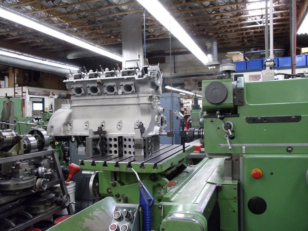
First order was to get the block on the machine (FP4NC) and aligned square with the spindle....
To do this i retained the crank shaft fitted to the block complete with thrust bearings in place......
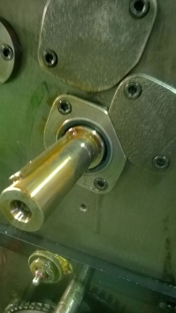
To align the machine with the block , i am using the rotation of the crank and the rotation of the horizontal spindle......I made an extension for the front end of the crank...cylindrical (.750" OD)
with a hole through.... A bolt through holds the bar to the crank end....To this bar i have fitted a right angle bar (extension boring bar form a Wohlhaupter boring head kit)....
In the spindle i fit a similar arrangement....By rotating the crank the arm will describe a circle that is at at right angle to the axis of rotation (crank). The same applies to the machine spindle
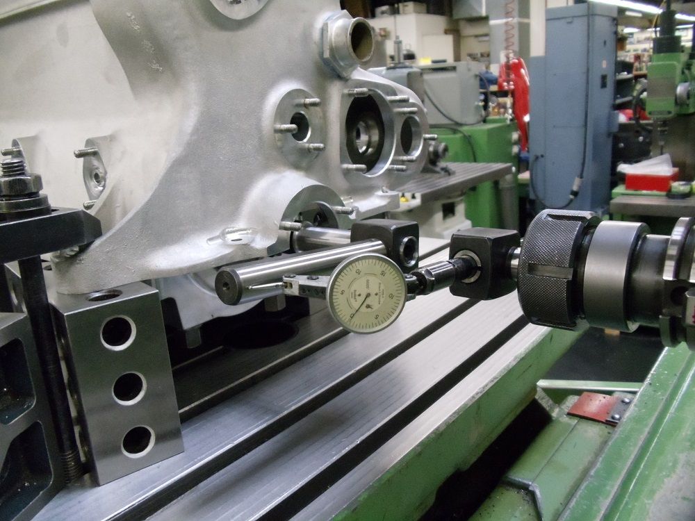
and its right angle test bar....Now if you fit an indicator to one of the arms and indicate to the opposite bar any difference as the two are moved together shows the difference in alignment...
Of course indicating while rotating both is a bit tough, so i do this test in "quarters". The exact square of the arms is not an issue so long as the testing point along the bar is the same for each
test position...and using round bars while making reading a bit more fiddly...removes additional errors that might be induced by an arm that was not truly flat to the indicator.....Oh and you must
be sure to bias the
crank against the thrust going the same direction for each test point....Any axial move from the crank will negate the indicated results.
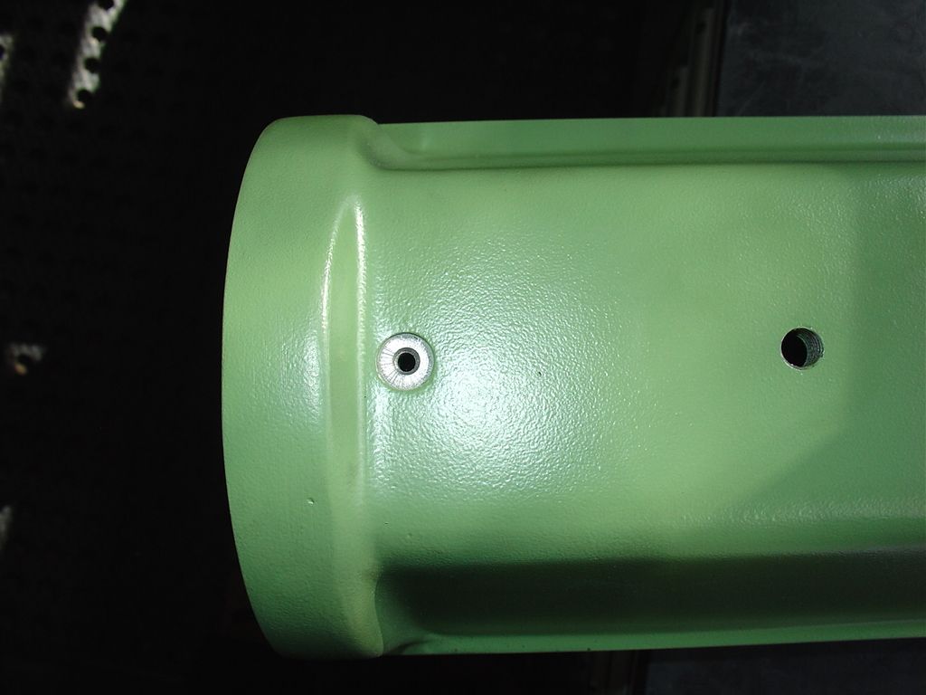
Here is the basic setup.....
![]()
![]()
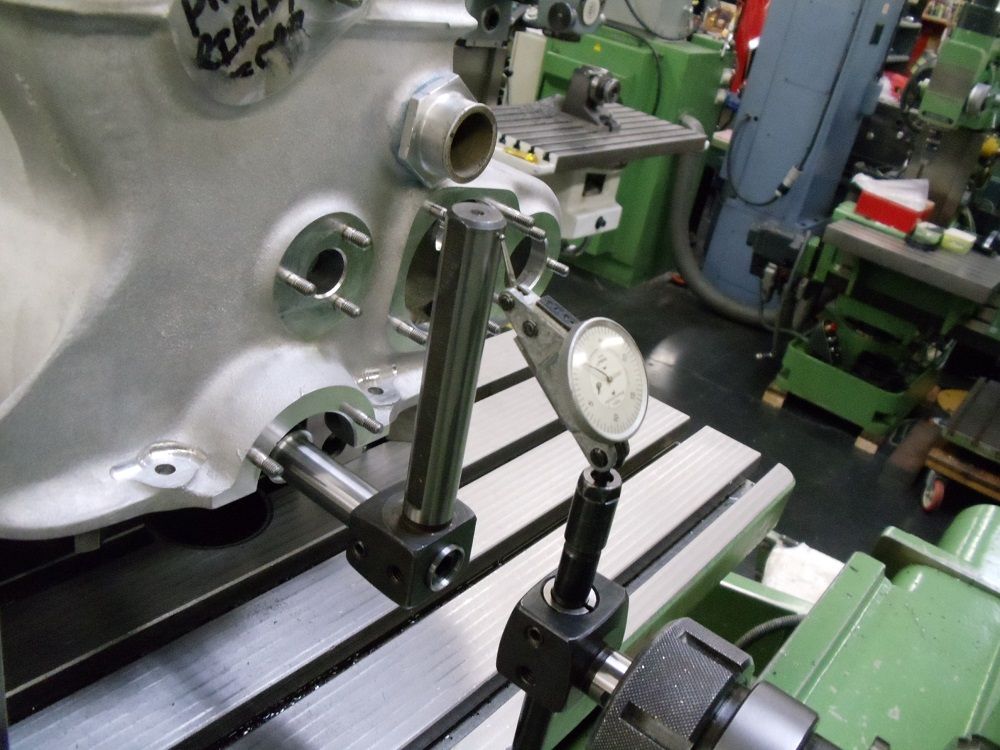
Here is where having the "tool Makers" table is worth its weight! Getting everything true as indicated within a few tenths is so much easier than shimming and clubbing the part about.
Also of note to mention is that having at least 4 good 2,4,6 blocks and lots of bolts and clamps is a must for doing horizontal setups.....
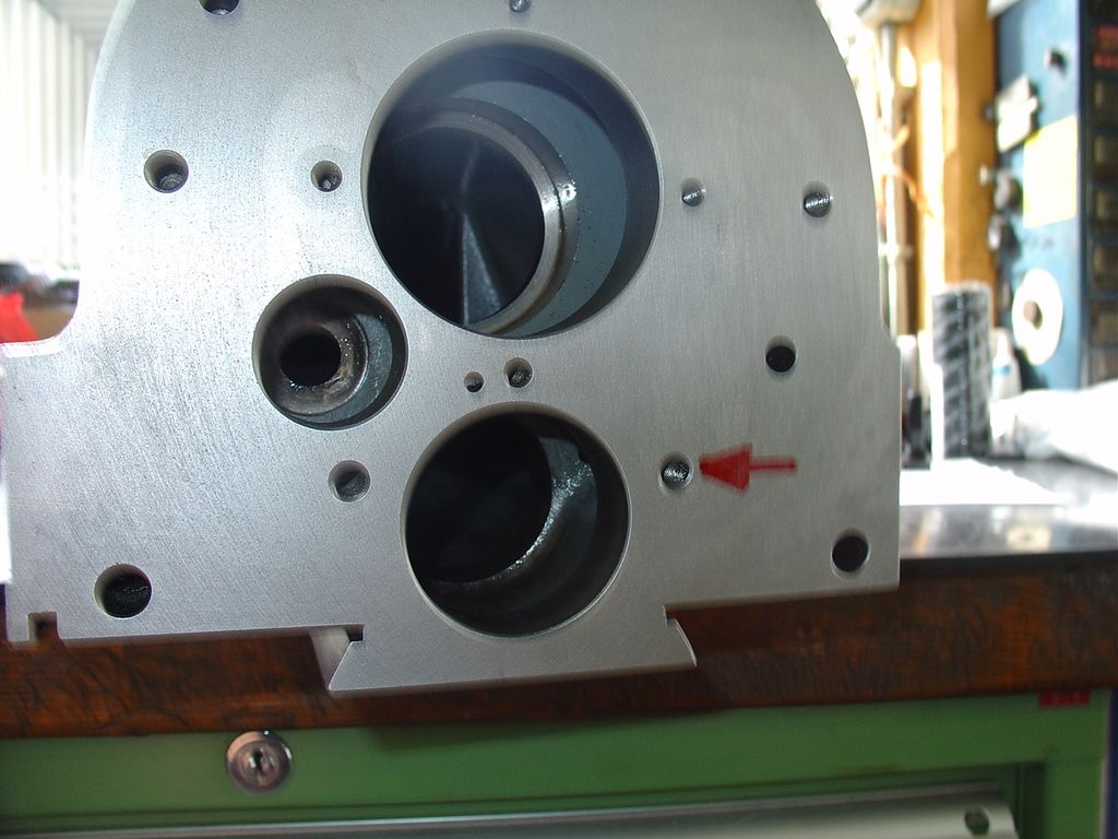
Once the block was in tram....the next operation here to "Map" the location of all the housing bores for all the bearings and shafts that are involved in the front gear train that drive the cams.
A drawing was done in "SurfCam" of all gear centers. I will use this layout later to relocate the gear centers as needed.
The datum used here is the crank center...dialed directly off the crank after the alignment was complete...
![]()
Note that the direction of the axis is reversed on the drawing....that is because when running horizontal the part is seen as being machined from the back side...and the drawing reflects this.
Overall view of the setup......
![]()
More to follow...
Cheers Ross
Have a very good customer who has been running a Typo 61 (Maserati Birdcage) for the last few seasons....Gives the car a good workout and this year he is changing out
the engine block, for a new (reproduction) unit. Engine cases have a lifespan. This is a 4 cylinder block with wet liners (CI) originally built as a 1600CC design...and expanded over
the years by the factory to its final 2.9 L displacement. Expanding the bore has the down side of reducing the internal thickness of the some of the block structural members, and hence the reduced life..
Replacement blocs come from Brian Heart in the UK.......So much for the short history.
as with things made on a "Short or limited Run" basis often differences exist between "similar" parts.....no exception in the case of this block!
First step in making a block swap is to measure everything, and do a test assembly.This includes laying the crank, and fitting all the cam drive gears and cylinder head.....
The engine is an in line 4 having twin overhead cams.....operating two valves per cylinder.....The head is removable but has no head gasket....It seats directly on top of the
iron cylinder liners for sealing the combustion....The coolant is contained within the block via an "O" ring that encases the perimeter of the block where it mates to the head....
All drives on the engine are gear driven....no belts anywhere. This means that the position of the gear centers needs to be controlled closely.
In this case there was a problem discovered when doing the "mock" up There was no gear lash between the crank gear and the first cam idler gear ...in addition there was little to no clearance between
the first idler and the 2and ...but excessive lash (clearance) between the 2and idler and the gear in the head......
It was decided that these conditions needed to be corrected before the block could be put into service...Enter "Yours truly".....................
First order was to get the block on the machine (FP4NC) and aligned square with the spindle....
To do this i retained the crank shaft fitted to the block complete with thrust bearings in place......
To align the machine with the block , i am using the rotation of the crank and the rotation of the horizontal spindle......I made an extension for the front end of the crank...cylindrical (.750" OD)
with a hole through.... A bolt through holds the bar to the crank end....To this bar i have fitted a right angle bar (extension boring bar form a Wohlhaupter boring head kit)....
In the spindle i fit a similar arrangement....By rotating the crank the arm will describe a circle that is at at right angle to the axis of rotation (crank). The same applies to the machine spindle
and its right angle test bar....Now if you fit an indicator to one of the arms and indicate to the opposite bar any difference as the two are moved together shows the difference in alignment...
Of course indicating while rotating both is a bit tough, so i do this test in "quarters". The exact square of the arms is not an issue so long as the testing point along the bar is the same for each
test position...and using round bars while making reading a bit more fiddly...removes additional errors that might be induced by an arm that was not truly flat to the indicator.....Oh and you must
be sure to bias the
crank against the thrust going the same direction for each test point....Any axial move from the crank will negate the indicated results.
Here is the basic setup.....
Here is where having the "tool Makers" table is worth its weight! Getting everything true as indicated within a few tenths is so much easier than shimming and clubbing the part about.
Also of note to mention is that having at least 4 good 2,4,6 blocks and lots of bolts and clamps is a must for doing horizontal setups.....
Once the block was in tram....the next operation here to "Map" the location of all the housing bores for all the bearings and shafts that are involved in the front gear train that drive the cams.
A drawing was done in "SurfCam" of all gear centers. I will use this layout later to relocate the gear centers as needed.
The datum used here is the crank center...dialed directly off the crank after the alignment was complete...
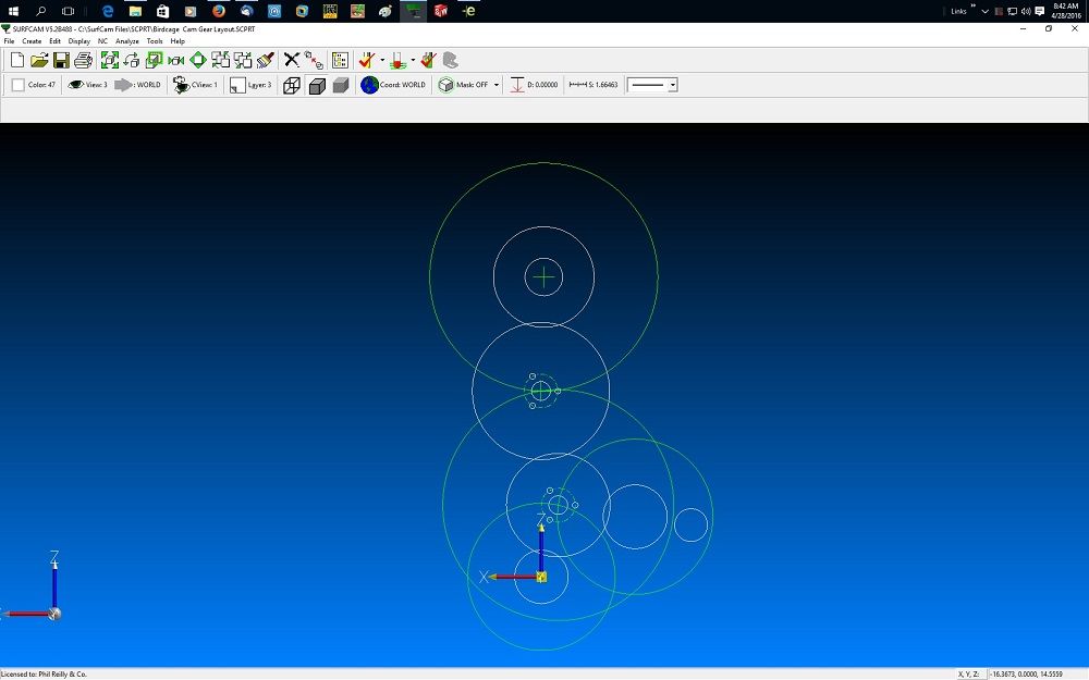
Note that the direction of the axis is reversed on the drawing....that is because when running horizontal the part is seen as being machined from the back side...and the drawing reflects this.
Overall view of the setup......
More to follow...
Cheers Ross