Quantcast
Channel: Practical Machinist - Largest Manufacturing Technology Forum on the Web - Deckel, Maho, Aciera, Abene Mills
Viewing all 2110 articles
Browse latest View live

Advice / Help needed on 1952 FP-1 Spindle

$
0
0
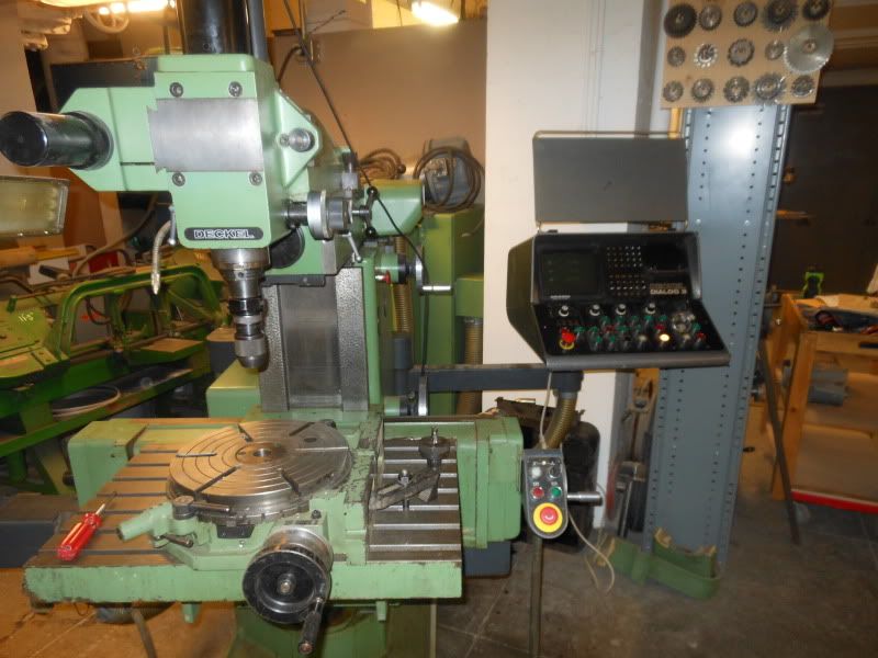
I am in the process of restoring my 1952 FP-1 and have discovered that the quill on the vertical head is marked in millimeters while the rest of the machine is emperical. Doubting that Deckel would have originally supplied the machine like this, I now have no idea what vintage the vertical head is and am thus wondering what its bearing configuration is.

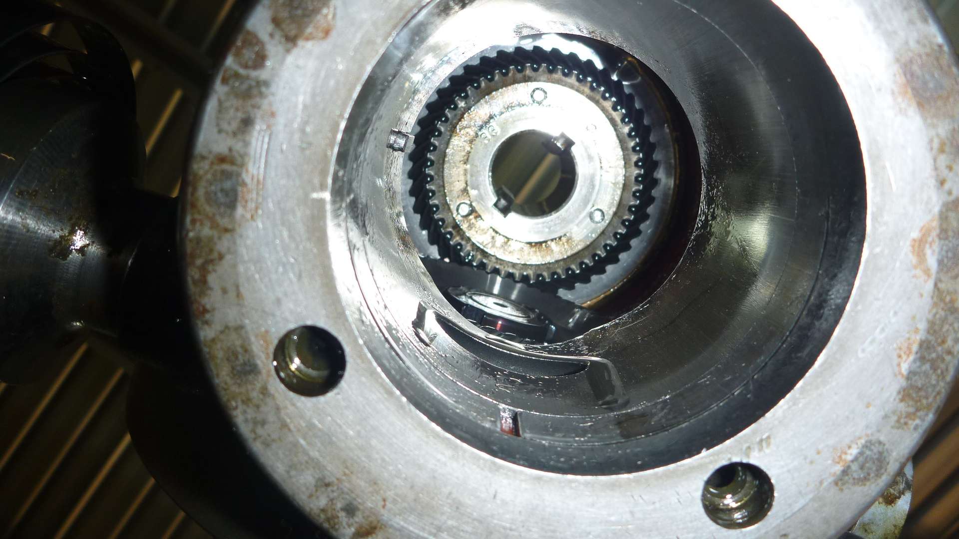
I have removed the quill from the cast housing but have not removed the spindle from the quill. The 2 uppers are ball bearings but I don't know the configuration of the lower bearings. (Needle vs bushing etc.) I hesitate to remove the spindle from the quill because it appears to be original. The locking ring on the spanner nut is unadultrated and the spindle feels very smooth and has no noticable play.

I'm wondering if someone in the past has scavanged parts to assemble this vertical head because the gear shaft, (that raises and lowers the spindle,) fits so tightly in the housing that you have to tap it into place. It can be rotated with a wrench, but not by your bear hand, and certainly not by the return spring. This is an easy fix in the lathe with some gentle emory cloth, but it does make you wonder about this machine's history over the past 60 years!

My inclination is to leave the spindle alone but wanted to ask for advice.

Thanks for any input,
Gaylan

Removing the knee on Abene VHF3

$
0
0
Could I get some pointers on the best way to remove the knee? I bought Milacron's Abene and am doing a tear down/cleaning/repaint; the table and saddle came off nicely-had to make a tool to unscrew the hand wheels.
The current status is that I'm looking down into the hole where the saddle was into the gearbox to the left rear. The hand wheel shafts have been removed but the longitudinal shaft behind the big black cover plug (the one that looks like you use a quarter to remove it) remains in place. The gearbox appears to be on a cassette type of housing that slides out intact. But the question of the day is what comes loose next to enable the removal of the gearbox? I'd like to leave as much assembled in the knee as possible to allow cleaning and exterior painting. Would appreciate some advice from those of you who have been here before. Thanks.

NCT500 as spin table?

$
0
0
Does anyone know if it's readily, easily (ie, without cutting wires/hacking into the control) possible to configure the NCT500 rotary table to spin constantly--while at the same time, be able to move the other axis at a different feed rate than the table? Have some circles and spheres to generate via boring head, and need to be able to move X and Z independently of the table rotation. Handwheel movement of X and Z in Mode 1 would be acceptable, but I can not figure out how to get the table spinning in Mode 1.

Is this SIP?

$
0
0
Hello all,

I found this with allot of swiss machines and tooling. I cant place it but have been told it might be SIP


Thanks for taking a look,

Coz

Deckel Engraver accessory

$
0
0
I have a Deckel engraver accessory that I want to sell but I'm really not sure what Deckel call it.
It's the scroll chuck (with inner and outer jaws) that's worm driven like a mini rotary table
Click image for larger version. 

Name:	Dec01.jpg 
Views:	37 
Size:	56.6 KB 
ID:	69389
Thanks & Regards
Paul Churchill
Attached Thumbnails
Click image for larger version. 

Name:	Dec01.jpg 
Views:	N/A 
Size:	56.6 KB 
ID:	69389  

Question about Lubricating Elevating Screw on FP1 (vintage 1952)

$
0
0
The FP1 is getting close to being finished and I ran into another question.

In looking at the lubrication instructions in the manual, it calls for daily oiling of the elevating screw. However, it simply shows a schematic of the machine and points to the dust cover for the screw....it does not go into specifics.

I assume you are to use the large oiling port that is on the bevel gear cover but I'm wondering why Deckel would have used such a large port? (It is the largest oiling port on the machine.) I suppose one could simply apply oil directly to the screw via a squirt can filled with Mobil D.T.E. heavy medium oil, and just use the port for the gears.


Thanks for any insight as to the proper method.
gm

SHW mill

$
0
0
Click image for larger version. 

Name:	ImageUploadedByTapatalk1360697163.230903.jpg 
Views:	73 
Size:	31.1 KB 
ID:	69503

Click image for larger version. 

Name:	ImageUploadedByTapatalk1360697192.210750.jpg 
Views:	76 
Size:	31.2 KB 
ID:	69504

This is my new to me SHW mill
It has a turret head with vertical, slotting and horizontal functions.
I am really pleased with it although I can not get the dro to work.
SHW are still producing machines in Germany. I have emailed them to see if I can get a manual.
John
Attached Thumbnails
Click image for larger version. 

Name:	ImageUploadedByTapatalk1360697163.230903.jpg 
Views:	N/A 
Size:	31.1 KB 
ID:	69503   Click image for larger version. 

Name:	ImageUploadedByTapatalk1360697192.210750.jpg 
Views:	N/A 
Size:	31.2 KB 
ID:	69504  

DECKEL FP1/ RIKEN, (Vertical Head) - LEAKING OIL AROUND QUILL?

$
0
0
Hi everyone, got bit of an issue I'm trying to resolve with the vertical head on my little RIKEN milling machine.
I dissasembled yesterday, and have satisfied myself the leak emintates from inbetween the O.D. of the quill & head casting, rather than the quill & tapered spindle body (as I initially thought).
The design being closed based on the deckel fp1 (Mk2), and possibly closest to the "Alexander master toolmaker", wondering if anyone familiar with the designs mentioned might be able to shed some light on:

#roughly what measures were built in to prevent leakage i.e seals etc, (because I'm seeing a distinct lack of any, other than the close fit of quill which is possibly fine when new)

#anyone know if the split clamping ring for the quill in the bore of the head can be removed? (see picture) or would it have been pressed/heated in?
I see this as being the most definite remedy - remove & machine a recess for a lip seal?

# what purpose does the bakelite ring/washer serve? it sits pretty freely atop the spindle, on the lock nuts responsible for thrust bearing preset.


-Would be interested to hear any other imput as to how to go about fixing this-

-also took the spindle apart and adjusted bearings, replaced the lubricating felts etc (pic is the before shot - hence why they look abit anemic and pretty scruffy-


Anyway can provide more detail later, but just thought I'd get the topic up quick - to get some diagnostics people on the job

THANKS

Fitting a Digital Readout

$
0
0
I have an Alexander Master Toolmaker milling machine, a few years ago I fitted it with a set of three cheap linear scales to give me a sort of poor mans digital readout system.

This has worked extremely well and served its purpose, but I am now wondering if I should go the whole hog and fit a full three axis or maybe just an XY axis digital readout system. I like the look of some of the features like bolt hole circles and co-ordinate curve milling etc. I think I could probably manage with a two axis DRO and retain the existing digital scale for the Z axis.

I have been looking at the ones on the Allendale Machine-DRO website.

My question is:-

Has anyone fitted a system to an Alexander or a Deckel FP1 which is essentially the same. Did you encounter any problems etc.

Thanks

Phil

A little help with FP3NC Dialog 3 new to me

$
0
0
Hi
We got this mill about 6 months ago and I finally had a chance this week to set it up.


The mill is wire to 240 three phase and has the factory boost transformer. I used the +% taps to get a final voltage of ~389. I do not have the manuals or flip cards but am working to get the cards and manuals. Everything that I have tried so far has worked all speeds, tool changer, CRT, lube, spindle lock and DRO. I have the control set on 1 for manual mode. The DRO is now in mm but I would like to switch it to inch, how do you do that? How do you zero the DRO? I'm sure this mill will need new batteries, what problems should I expect to see until they are changed? Where is the best place to check to see that it is getting lube (I can hear it and the light comes on)? Any help with the manuals would be great.

Andy

Rambaudi Milling Machine UR 60 New Hampshire CL

$
0
0
This looks like a very nice machine. I'm afraid to ask the price.
Pictures for posterity.

Rambaudi Machine
Attached Thumbnails
Click image for larger version. 

Name:	Rambaudi Mill 1.jpg 
Views:	N/A 
Size:	36.1 KB 
ID:	69791   Click image for larger version. 

Name:	Rambaudi Mill 2.jpg 
Views:	N/A 
Size:	30.1 KB 
ID:	69793   Click image for larger version. 

Name:	Rambaudi Mill 3.jpg 
Views:	N/A 
Size:	31.9 KB 
ID:	69794  

Abene Photos of Factory Refurbed Machine

$
0
0
Click image for larger version. 

Name:	Abene Refurb 1.jpg 
Views:	177 
Size:	93.9 KB 
ID:	69975Click image for larger version. 

Name:	Abene Refurb 2.jpg 
Views:	164 
Size:	95.4 KB 
ID:	69976The cost of rebuilding a VHF 3 is $20,000-$25,000 depending on what parts have to be replaced.
Attached Thumbnails
Click image for larger version. 

Name:	Abene Refurb 1.jpg 
Views:	N/A 
Size:	93.9 KB 
ID:	69975   Click image for larger version. 

Name:	Abene Refurb 2.jpg 
Views:	N/A 
Size:	95.4 KB 
ID:	69976  

Deckel FP2 chain tension

$
0
0
Greetings experts...

I am de-bubbafying my recently acquired 1962 FP2. In the attached photo of the drive chain you can see too much chain slack. In the center of the run there is 42mm/ 1.7" of slack.

Des this mean "Hello Franz" again:bawling:or is it possible to remove a link and not end up too short?

Also...can anyone tell me the diameter of the spindle handwheel that bolts to the top pulley? (Bubba used mine for a frisbee I guess)

Thanks,
Greg Q
MelbourneClick image for larger version. 

Name:	image.jpg 
Views:	35 
Size:	91.8 KB 
ID:	70063
Attached Thumbnails
Click image for larger version. 

Name:	image.jpg 
Views:	N/A 
Size:	91.8 KB 
ID:	70063  

Cutting 2080 groove on a C scope?

$
0
0
Any good Ideas how to cut the 2080 groove on this Center scope. It's a very nice Nippon Kogaku but I don't think the arbor will come off. It would be hard to hold in a lathe or to try and use a boring head to cut it. Do they make 40 to 40 adapters?


Andy

FP-NC Single point Thread Milling

$
0
0
Thought some of you might be interested in this little job.....
This is a family of work i do from time to time using different sizes and different thread pitch...
The point here is to take a new connecting rod , in this case Carrillo, and prep the ID to accept Babbitt.

Of course the first question is why would anyone use a poured white metal bearing on the big end of a con rod.....
For many of the cars i work on there are no suitable thin wall bearings, plus many of the older cranks are plain steel...not nitrided , and finally
using a poured bearing allows grinding the crank the very least and extends the life of the old parts.....

OK so here is the drill:

to start i mount a standard "lathe" style threading boring bar in a collet chuck.
I favor the round metric bars by Sandvik. I like the round versions because they work with the indexing bushings that i use on my Romi in my MultiFix holders.
Since the boring bar holders are metric (40 mm) i am tied to a metric busing to adapt from the 40 to the bar diameter...in this case 16mm.


The collet chuck of choice here is a TG100. I use the TG setup on all my larger tools. I believe that it gives better grip than the same sized ER setup.(longer shallower taper on the TG's= more holding power)


OK here is the basic setup. The sides of the big end of the rod are flat and parallel, so i grip in the vise on parallels. To give a repeatable location i am using a small expanding mandrel that is from my connecting rod boring machine.
(Berco AB 320). The rod machine has a selection to these mandrels of varing sizes with different jaws to cover quite a range of sizes...very handy , and i use them on the boring machine, on the lathe ond on the mill as you see.


It is important here to be careful of the closing force on the rod as you can make the big end bore oval if you get too husky tightening the vise.

I do check each rod for position before running the job. Over tightening will show when the bore is clocked...
Here is the job in process....the cut is started below the top of the rod and ends before it exits the rod at the bottom. This gives a dead ended cut with no runout to help secure the babbitt.


More to follow...
Cheers Ross

Need Help Identifying an FP1 part.

$
0
0
Well.....I'm very embarrassed to have to ask this question, but after 2 weeks of racking my brain, scouring the internet, searching every parts manual I can find, I have to admit that I'm stumped! (Did I mention very embarrassed!!!!)

I'm getting close to finishing my 1952 FP-1, my first venture into the workings of these wonderfully made machines.

After carefully tearing down the vertical spindle, numbering and labeling all the bearings and races, I find this thrust washer lying on the bench where I had been doing the dis-assembly. For the life of me, I cannot find where it goes!!! (God this is killing me....)

Anyway, as you can see from the attached photo's, it has a pin that apparently indexes it to a rotating shaft, but I cannot find this part on any of the documents I have.

The only parts with rotating shafts that I have disassembled are the vertical head, the main power shaft of the upper transmission, (the shaft which the drive pulley mounts to), the horizontal spindle, and the longitudinal saddle travel lead screw.

After all of my searching...I'm beginning to wonder if one of my "buddies" set this on the bench just to mess with me....

So, with much humiliation, I've come to the guru's of Deckel with this question: Does anyone recognize this thrust washer as a Deckel FP1 component and if so, where the hell does it go!!!! (I'm loosing my mind here!)

Deepest thanks!
Gaylan
Attached Thumbnails
Click image for larger version. 

Name:	Thrust Washer.jpg 
Views:	N/A 
Size:	88.4 KB 
ID:	70434  

LIP Surface Grinder Parts

$
0
0
I have a LIP model 515 surface grinder that I'm working on and I need to purchase some parts. I have sent LIP in France a couple of emails asking about parts and have never gotten an answer. I suspect that they don't sell to the US because they don't have a sales presences here. Is there somebody in Europe that would act as a go-between LIP And myself. I have a parts list and have the part numbers for what I need.
Thanks!
Todd

Dialog 4 NC-programs? (Or working postprocessor for HSMXpress...)

$
0
0
Hello,

I've been trying to get our Deckel FP3NC and HSMXpress to work nicely together. At the moment I can get post processor to post a program that will somewhat run on the control, but the movement is jerky.

Does anyone have a nicely working CAM-generated nc-file that you could share? I could try to investigate what is wrong with the current post...

Br, Mikko

Aciera Old Style F3 Spiral Milling Gearbox

$
0
0
I have a spiral milling gearbox and differential dividing head for old style Aciera F3. The gearbox contains the Module 1.5 transfer gears, one 56 tooth Module 1 change gear and an abused 28 tooth Module 1 change gear which was mounted on the dividing head drive shaft. All but the 28 tooth gear are pristine.

I've posted a wanted request for a full set of Module 1 change gears.

My setup includes 3 arms, two with 32 tooth, Module 1 idler gears and one with the 56 tooth, Module 1 change gear. Is this a complete set of arms? There's a clip inside the gearbox cover that seems it might be a storage location for an arm.

I seem to have all the bushings need for the hardware on hand.

I have no detailed documentation for the gearbox.

I'm looking for a photo of a typical change gear setup to compare with my hardware as well as any documentation listing practical gear combinations. I've made a spreadsheet for gear combinations and resultant milling pitch but not sure that it reflects the intended gear combinations. I have the list of 12 change gears and the overall pitch range from a brochure page.

There's one interface problem. The gearbox mounts properly to the X-Axis lead screw spline and the gearbox mates flush to the end of my 331 table; however, the mounting hole in the gearbox is about 3/4 bolt diameter off from the tapped hole in the table. Does this suggest a gearbox version mismatch?

Thanks

Aciera F3 Head Handling and Storage

$
0
0
I have and old style Aciera F3 with:

- Geared vertical head
- High speed head modified with 1hp DC motor
- Slotting head
- Horizontal overarm
- 3" Y-Axis ram riser
- 331 Table

I'm an old guy and handling the high speed head (80# total with new motor) and slotting head have caused serious pain and muscle damage. I can handle the high speed head only by disassembling motor and head and the motor is very awkward. The other accessories may soon be beyond my manual capability.

I'm looking for a compact system to handle the heads, riser and 331 table without manual lifting. My shop overhead is very low and a rail/hoist system isn't practical and interfaces of such a system with storage racks seems to take more floor space than I'd like. Also, locations of lifting eyes or straps is awkward. The CGs of the heads aren't ideally located for balanced handling, particularly for the high speed head with the heavy motor.

I'm considering a commercial, manual hydraulic fork lift but there are some interface problems that would require modification and I'd prefer an electrical fork drive with vertical lead screw . . . hydraulics can be twitchy and I want precise vertical control since I plan to use stabs and tube sockets mounted on the heads as an interface. Also, I feel that the lead screw design has fewer failure modes.

My current plan is to make a small fork lift with a cabinet at the back which would hold accessories other than the heads and overarm. This would nest with a wall mounted rack for the heads and would occupy very little floor space when stowed. Floor space is at a premium. The back cabinet on the lift would provide a counterbalance weight for the overhung head weight and convenient storage. I'd include a fixed weight that would counterbalance even if the storage cabinet went light. The lift legs would straddle the F3 base and the wall mounted cabinet. The forks would be adjustable to accommodate the 331 table as well.

I'm looking for other ideas before committing to this design. My requirements are:

- Compatible with low overhead (the top of the high speed head motor almost kisses the overhead)
- Very small total footprint including accessory stowage and handling gear
- Safe handling of all heavy accessories without manual lifting
- Very quick mate/demate with heads and storage rack for quick head exchange
- Some head modification allowed, e.g., installation of stab sockets, but must not interfere with head function

I'd be interested in any implemented solutions that meet these requirements.

Thanks
Viewing all 2110 articles
Browse latest View live


<script src="https://jsc.adskeeper.com/r/s/rssing.com.1596347.js" async> </script>